Utilizziamo i cookie per assicurarti di offrirti la migliore esperienza sul nostro sito web.
Rimanete aggiornati con KCVENTS Soluzioni di ventilazione & HVAC
Iscrivetevi alla nostra newsletter per le ultime novità di ingegneria aeraulica, gli aggiornamenti sui sistemi ERV/HRV ad alta efficienza energetica e soluzioni HVAC ecocompatibili.
Ricevete per primi guide tecniche esclusive, informazioni sulle capacità OEM/ODM personalizzate e novità sulle fiere internazionali direttamente da KCVENTS.
Static Pressure Explained: How to Read a Fan Curve and Choose a Fan
Static pressure is the resistance a fan pushes against. Learn how to estimate it, read a fan curve against your system curve, and find the real operating point.
Static pressure is the resistance a fan has to push against: duct friction, elbows, filters, grilles, coils and the outlet hood. It is measured in pascals (Pa) or inches of water gauge (in. w.g.). The airflow printed for “0 Pa” or “free air” is the most a fan will ever move. In a real system it moves less, at the point where its fan curve crosses your system’s resistance curve. Find that point before you buy, and the room gets the airflow you designed for.
Fan operating point calculator
1. Your system at the design airflow
m³/h
Pa
The static pressure of the longest run at that airflow: straight duct (from the ductulator), fittings, filter, grilles, hood.
2. The fan curve (from the fan’s datasheet)
Portata d'aria m³/h
Pressione statica Pa
The values filled in are an example. Replace them with points read from your fan’s curve at the speed you will run it. Leave a row empty to skip it.
Operating airflow
–
Static pressure there
–
This fan meets the design airflow. If it is well above it, an EC fan can be slowed down: see the fan laws below.
This fan falls short of the design airflow. Lower the system’s resistance (bigger ducts, fewer elbows, a cleaner filter) or choose a fan with more pressure at this airflow.
The fan cannot reach the system curve within the points you entered: at every airflow listed, the system needs more pressure than the fan gives.
The fan still has pressure to spare at the last point you entered. Add the curve at higher airflow to find the operating point.
Enter a design airflow, its static pressure and at least two points of the fan curve.
Fan curveSystem curve● Operating point○ Design point
Static, velocity and total pressure
Air moving through a duct carries two kinds of pressure. Pressione statica pushes on the duct walls in every direction; it is what the duct, filter and grilles use up. Velocity pressure is the pressure of the air’s motion, and it depends only on how fast the air moves and how dense it is. Their sum is the total pressure.
Total pressure = static pressure + velocity pressure Velocity pressure = ρ × V² ÷ 2 ≈ 0.6 × V² (Pa, with V in m/s and air at 1.2 kg/m³)
In a 250 mm duct carrying 1,000 m³/h, the air moves at about 5.7 m/s, so the velocity pressure is about 19 Pa. Fan tables for ducted fans are usually given in static pressure, so compare like with like: a system total in static pressure against a fan curve in static pressure.
The numbers are small. Greenheck’s Fan Fundamentals notes: “Static pressures in fan systems are typically less than 2 in. of water gauge, or 0.072 Psi.” One inch of water gauge is about 249 Pa. Small as they are, the same guide warns that “accurately estimating the static pressure is critical to proper fan selection.”
Where the static pressure comes from
Add up every part the air passes through on the longest run, at the design airflow:
Straight duct: friction rate × length. The ductulator gives the friction rate for your duct size and airflow, and its Check tab gives the loss for a given length.
Fittings: elbows, tees, reducers and dampers, as equivalent length or as pressure losses from the fitting maker.
Filtri: use the pressure drop the filter maker gives for the airflow, and design for the filter when it is due for a change, not when it is new. A filter loading up with dust raises the system curve, and the fan slides back along its curve to a lower airflow.
Grilles, diffusers, outdoor hoods and louvres: from the maker’s pressure–airflow data.
Heat exchangers, coils, silencers: from their datasheets at your airflow.
The total is the static pressure your system needs at the design airflow: the second number in the calculator above.
Fan curve, system curve and the operating point
“We have learned that a fan curve is the series of points at which a given fan model and size can operate at a constant RPM. The system resistance curve is the series of points at which the system can operate. The operating point is where these two curves intersect.” – Greenheck, Fan Application FA/100-24
The system curve is easy to draw from one point, because a fixed system follows a simple rule:
“For a constant system, with no change in damper settings, etc. the pressure at a given flow varies as the square of the airflow.” – Greenheck, Fan Application FA/100-24
So if your system needs 250 Pa at 1,000 m³/h, it needs about 62 Pa at 500 m³/h and 1,000 Pa at 2,000 m³/h. Doubling the airflow through the same ducts takes four times the pressure. This is why adding a second, bigger fan to an undersized duct disappoints: most of the extra pressure goes into friction, not into airflow.
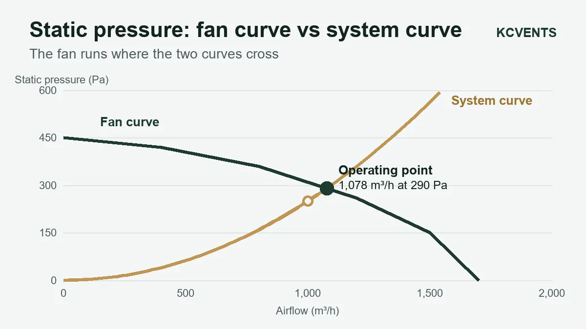
The calculator does exactly this: it draws the system curve through your design point, draws the fan curve through the points you enter, and finds where they cross. With the example values, the fan settles at about 1,078 m³/h and 290 Pa, 8% above the 1,000 m³/h the system was designed for.
The calculator’s example: the system needs 250 Pa at 1,000 m³/h (open circle); the fan curve crosses the system curve at 1,078 m³/h and 290 Pa (filled circle).
Fan laws: what changing the speed does
For one fan in one system, airflow changes in proportion to the fan speed, static pressure with the square of the speed, and power with the cube. Greenheck’s worked example takes a fan from 10,000 CFM at 1,000 rpm, 1.50 in. w.g. and 5.00 bhp to 12,500 CFM: that needs 1,250 rpm, the pressure rises to 2.34 in. w.g. and the power to 9.77 bhp. A 25% increase in airflow costs 95% more power.
The same law works in your favour. An EC fan that delivers more than the design airflow can be slowed down: running at 80% speed gives 80% of the airflow for about half the power (0.8³ ≈ 0.51). That is the practical case for EC inline fans with a speed controller: pick a fan with some margin, then trim it to the design airflow on site.
A good operating point, and a bad one
Near the middle of the curve. The U.S. DOE fan sourcebook: “Moving a fan’s operating point away from its BEP increases bearing loads and noise.” The best efficiency point (BEP) sits well inside the curve, away from both free air and shut-off; the fan maker can mark it on the curve.
Not on the steep, high-pressure end. Many fans have an unstable region near shut-off. Greenheck: “Fan selection close to, or to the left of the surge curve, is not recommended.” A point there can hunt and roar when a filter loads.
Not grossly oversized. The same sourcebook: “Fans that are oversized for their service requirements do not operate at their best efficiency points.”
Mind the system effect. Datasheet curves are measured with a clean inlet and outlet. The DOE sourcebook warns that “The use of multiple elbows close to a fan inlet or outlet can create a costly system effect”. Leave a straight run of duct before and after an inline fan.
Which fan type for which pressure
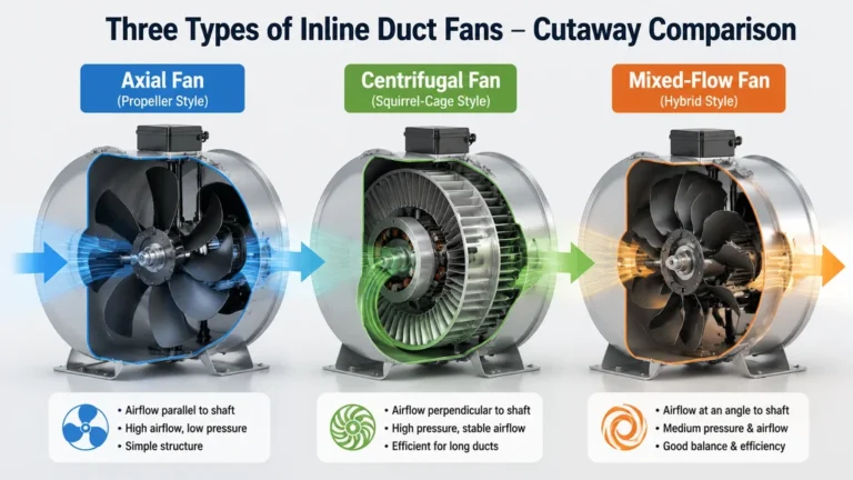
The fan type sets the shape of the curve, so the system pressure narrows the choice before you compare models.
It is the pressure the air exerts on the duct walls, above or below the air outside the duct. A fan has to create enough of it to overcome the resistance of the ducts, fittings, filters and grilles at the airflow you need.
How is static pressure measured?
With a manometer connected to a static pressure tip or a tap in the duct wall. Greenheck’s Fan Fundamentals describes the simplest form: a water-filled U-tube where “A pressure differential between the duct and the atmosphere will cause the water level in the manometer legs to rest at different levels.” Digital manometers read the same thing in Pa or in. w.g.
Does higher static pressure mean a better fan?
No. A fan with a high maximum pressure is right for a high-resistance system and wasteful for a short, open one. What matters is the airflow the fan delivers at your system’s pressure, near the middle of its curve.
What is external static pressure?
For packaged equipment such as an HRV, ERV or air handler, it is the static pressure the unit can still deliver to everything outside it: the ducts, grilles and hoods. The unit’s own filters and heat exchanger are already accounted for. Size the ductwork so its total stays within that figure at the design airflow.
How do I convert Pa to inches of water gauge?
1 in. w.g. is about 249 Pa. So 100 Pa is 0.40 in. w.g., 250 Pa is 1.00 in. w.g. and 0.5 in. w.g. is about 125 Pa.
Why does my fan move less air than the box says?
The box usually gives the free-air airflow, at 0 static pressure. Every metre of duct, every elbow and the filter add resistance, so the fan settles further down its curve. Use the calculator above with your system’s pressure to see the real figure.
Send us the airflow and static pressure of your system. We will check it against the full curves of our inline, mixed flow, centrifugal and cabinet fans and propose the model and speed that hit the design point near the middle of the curve.