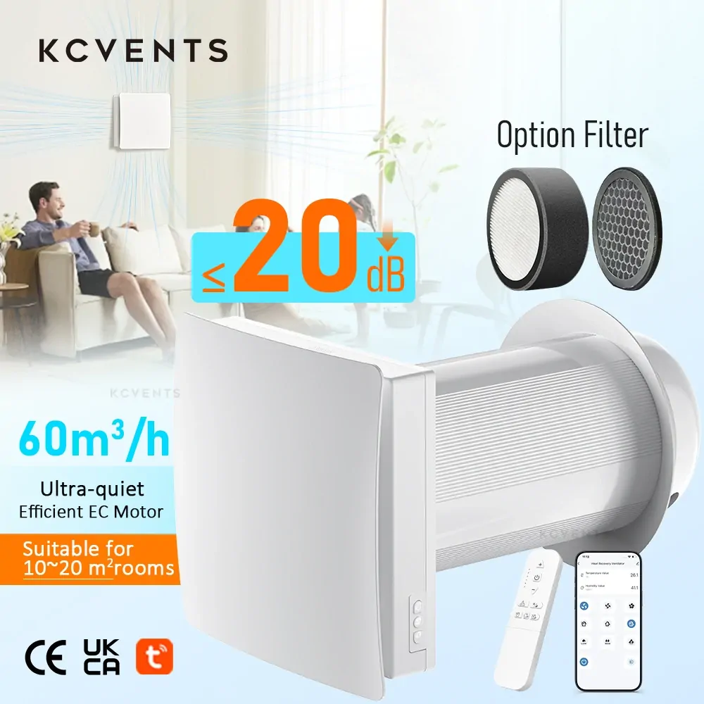
Multi-speed fans with electronic soft-touch or remote controls: Units equipped with digital push-buttons, capacitive touch panels, or handheld RF/infrared remotes contain microprocessors that govern power distribution. As documented in industrial electrical engineering references regarding motor controllers on Wikipedia: “If a momentary loss of supply voltage occurs, the contactor will open and not close again until a new start command is given. This prevents restarting of the motor after a power failure.” Domestic fans with digital control boards often mimic this safety behavior: when line power is cut and restored, they wake up in a de-energized “Standby” or “OFF” state, requiring a manual button press to resume operation. Furthermore, universal RF hubs like the BroadLink RM4 Pro cannot solve this reliably for every model: they learn fixed-code RF remotes within their supported bands, and cannot process rolling codes or long-press trigger commands.
EC motors with dedicated controllers: High-efficiency EC fans separate main AC power from motor control signals (such as 0–10V or PWM). As ebm-papst technical literature confirms: “If control voltage is applied or a speed setpoint is stored, the motor automatically restarts, e.g. after a power failure.” However, this automatic restart is an engineered design attribute of specific commercial-grade units, not a universal guarantee across all brands.
Decision point 2: will it remember the speed after a power cut?
Even if an exhaust fan powers back on automatically, automated cycling is counterproductive if the unit loses its calibrated speed setting and defaults to maximum noise or minimum airflow. Retaining the operating setpoint requires either mechanical retention or non-volatile digital memory.
To determine whether a unit will maintain its operating state during automated cycles, follow this three-step verification process:
Inspect the physical control interface: Fans featuring physical rotary potentiometers, multi-position slide switches, or stepped rocker selectors hold their calibration mechanically. Regardless of how many times an external timer switch for exhaust fan interrupts the circuit, the physical contacts remain in position.
Verify non-volatile memory specifications: For electronically regulated fans, look specifically for terms like “memory function”, “power-off resume”, or “EEPROM state retention” in the manufacturer’s engineering specification sheet. For example, the KCvents EC Motor Shutter Exhaust Fan explicitly documents a “10-speed … with memory function” control circuit. This guarantees that whether power is toggled via an in-wall timer or an external environmental relay, the fan resumes extracting air at the exact preset speed level rather than resetting to factory defaults. Conversely, budget multi-speed AC fans lacking non-volatile memory routinely revert to speed level 1 or shut down completely.
Submit a direct supplier verification checklist: When sourcing ventilation units for automation projects, request written confirmation from the manufacturer on three technical points:
Does the unit resume spinning automatically when mains power is applied without pressing a physical button or remote?
Does the controller store the active RPM / speed index in non-volatile memory during a total power interruption?
What is the duration of the microcontroller initialization delay from power restoration to actual impeller rotation?
Decision point 3: is the fan safe on a smart plug?
Plugging an exhaust fan into an off-the-shelf smart plug is an attractive shortcut, but it presents serious electrical fire and relay-welding hazards if motor ratings are ignored. Smart plugs are engineered primarily for resistive loads, such as incandescent lamps and convective space heaters, where current and voltage remain in phase.
Electric motors represent inductive loads. When an inductive circuit is energized, magnetizing the core causes an extreme initial surge. As noted in technical references on Inrush current (2026), AC motors and transformers “may draw several times their normal full-load current when first energized”. When the internal relay of a smart plug attempts to interrupt this inductive load, the collapsing magnetic field produces an inductive kick (back-EMF arc) across the miniature relay contacts. Over repeated cycles, this electrical arcing pits the contacts or welds them shut in a permanently closed state.
Smart plug manufacturers explicitly restrict inductive motor ratings to prevent equipment damage. For instance, in the published technical specifications for the Tapo P110, TP-Link specifies an absolute limit of “2990W, 13 A, 1/6 HP Motor” and issues an explicit hardware warning: “Avoid plugging in appliances with a motor/compressor higher than 1/6HP, such as an air conditioner.”
Furthermore, the smart plug’s own recovery state must be configured correctly. TP-Link documentation highlights that “Once the power or connection returns, your Tapo smart plug can take on a specific power status: — Previous power status (default) — Off (ideal for the heater) — On”. Similarly, smart switches flashed with open-source firmware like Tasmota rely on a configurable PowerOnState command to define relay recovery. If a smart plug defaults to “Off” after a brief grid flicker, your automated exhaust system stops operating entirely until manually triggered.
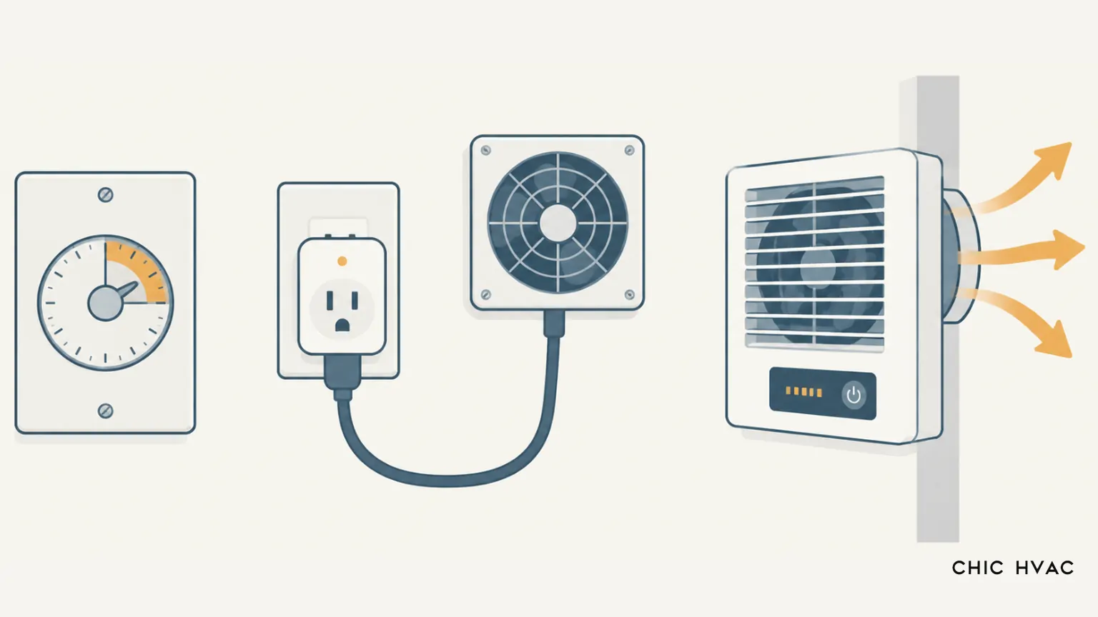
Engineering Recommendation: Where local code permits it, prefer an in-wall countdown timer or smart switch whose published rating explicitly covers your fan’s motor load (check the HP figure on the device label) over a plug-in adapter. This keeps the fan on permanent wiring and matches the load the switch was designed for. Reserve plug-in smart sockets for smaller fans that fall within the socket’s stated inductive rating.
Sizing the on/off cycle (duty cycle)
When you automate a fan using an intermittent ventilation timer, you cannot size the airflow capacity using continuous ventilation guidelines. An extraction fan operating intermittently must exhaust air at a significantly higher cubic-feet-per-minute (CFM) rate during its active window to achieve the cumulative air exchange required to dilute moisture and contaminants.
The Home Ventilating Institute (HVI, 2026) specifies standard continuous whole-house ventilation sizing at “0.35 ACH, or 5 CFM per 100 sq ft of floor area”. When addressing localized source control under ASHRAE Standard 62.2 and HVI guidelines, local bathroom exhaust requires an intermittent extraction rate of 50 CFM on demand (supplemented by a minimum 20-minute run-on time after room vacancy) versus a continuous baseline rate of 20 CFM.
To convert a continuous ventilation requirement into an intermittent duty-cycle schedule, apply the standard volumetric compensation formula:
Target Baseline: An enclosed utility room or light-commercial washroom requires an equivalent continuous dilution airflow of 40 CFM.
Duty Schedule 1 (30 minutes on / 30 minutes off): Required Airflow = 40 CFM × (60 / 30) = 80 CFM. The installed fan must deliver at least 80 CFM against actual duct static pressure during its 30-minute operational window.
Duty Schedule 2 (15 minutes on / 45 minutes off): Required Airflow = 40 CFM × (60 / 15) = 160 CFM. Shortening the cycle to 15 minutes per hour requires a larger extraction blower delivering at least 160 CFM to meet the same cumulative ventilation target.
Common mistakes
Cycling EC motors via external line-power relays: Repeatedly cutting line voltage to an EC fan discharges internal capacitors and subjects the inrush limiting circuit to continuous thermal stress. Instead of cutting 120V/230V mains power, automate EC fans via their native low-voltage 0–10V, PWM, or dry-contact run inputs.
Pairing timers with soft-touch digital control boards: Installing an external countdown timer on a fan equipped with digital push-buttons or touchpads often results in an unstarted fan. Once the timer cuts power, the internal electronic control board drops into an idle standby state and will not spin until someone physically presses the button.
Overloading smart plugs with inductive motor inrush: Plugging multi-hundred-watt inline utility fans into standard 10A/13A resistive smart plugs ignores inrush current, which can reach several times full-load amps. This leads to premature contact welding, rendering the plug permanently on or off.
Relying exclusively on fixed time clocks instead of environmental triggers: Fixed clock schedules fail to respond to dynamic moisture generation. Running a fan for 20 minutes at fixed intervals can over-ventilate during dry conditions (wasting conditioned heating/cooling) while under-ventilating after high-moisture showers. Integrate relative humidity (RH) or CO2 threshold sensors wherever possible.
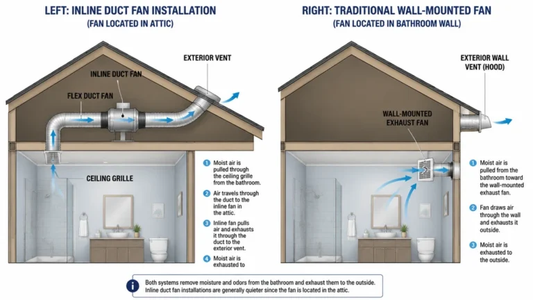
Omitting backdraft dampers: Intermittent ventilation means the fan is powered down for substantial periods throughout the day. Without an engineered spring-loaded backdraft damper or motorized gravity shutters, unconditioned outdoor air, sewer odors, radon, and insects will reverse-draft into the building envelope during the off-cycle.
Frequently asked questions
Can a smart plug turn an exhaust fan on and off automatically? Yes, provided the exhaust fan utilizes a simple mechanical switch that stays physically closed, and the motor’s full-load and starting current fall strictly within the smart plug’s inductive rating (typically 1/6 HP or lower). If the fan features an electronic control panel or remote receiver, cutting line power will cause it to revert to an unstarted standby mode.
Do exhaust fans lose their speed setting when power is cut? It depends entirely on the motor’s control architecture. Fans with mechanical rotary knobs, stepped toggle switches, or controllers engineered with non-volatile memory (such as KCvents EC shutter fans) automatically resume at their calibrated speed. Budget electronic fans with momentary push-buttons almost universally lose their speed index and reset to standby or minimum speed.
Can I control a bathroom exhaust fan with a Tapo or Tuya smart plug? You can, provided the fan draws less than the device’s explicit motor load limit (e.g., 1/6 HP on the Tapo P110) and is connected via an accessible receptacle. However, building codes in most jurisdictions require permanent in-wall wiring for bathroom exhaust ventilation. A dedicated, in-wall exhaust fan smart switch or rated countdown timer switch is significantly safer and code-compliant.
How long should an exhaust fan run on a timer? Under ASHRAE 62.2 and HVI guidelines, an intermittent bathroom exhaust fan should operate for at least 20 minutes following room occupancy to clear suspended aerosol moisture and prevent mold colonization within drywall and ceiling assemblies. For general air exchange duty cycles, runtime is calculated based on the required hourly CFM dilution rate.
Which type of exhaust fan suits scheduled timer operation? Fans whose control electronics are designed to survive power cycling, or that accept a low-voltage control signal, are the more reliable choice. Where a fan offers native Wi-Fi/Tuya scheduling or a wired speed controller, automating through that built-in control avoids repeatedly switching mains power at the motor. Always confirm the restart and speed-memory behaviour with the supplier before relying on an external timer.
Working with KCvents
As a specialized manufacturer of ventilation equipment and heat recovery systems, KCvents engineers fans designed specifically to streamline automated residential, commercial, and agricultural installations without requiring secondary third-party relays:
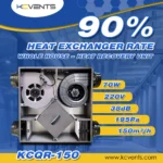
VT501-Wifi Single-Room Heat Recovery Ventilator: Features built-in Tuya App scheduling, integrated CO2 threshold linkage, and an automated 65-second cyclic reversing mode that balances continuous fresh air supply with heat recovery efficiency up to 90%.
EC Motor Shutter Exhaust Fan: Engineered for perimeter wall mounting in workshops and equipment rooms, with an automatic shutter that closes when the fan stops to reduce backdraft, and a 10-speed PWM controller specified with a memory function so a set speed is retained across power cycles.
Smart EC Mixed-Flow Inline Fan with Temperature & Humidity Controller: Features an external environmental probe that modulates impeller RPM dynamically based on real-time temperature and relative humidity triggers, eliminating the need for rigid on/off line switching.
EC Inline Fan With Stepless Speed: Supplied with a hardwired stepless speed controller, so airflow can be dialled in continuously rather than selected from fixed steps. Because the speed is set on the controller rather than inside the fan’s mains supply, it suits installations where the fan runs continuously and the airflow is tuned once at commissioning.
Whether you are designing a multi-family retrofit or specifying demand-controlled extraction for light commercial facilities, contact our engineering team to review system airflow requirements and duct static pressure curves. Explore our complete line of intelligent ventilation solutions or request a project quote directly through our contact portal.
Sources and further reading
ebm-papst (2020):Operating Instructions for RadiCal EC Centrifugal Fans (Manual R3G560-AQ04-01). Details on line-power cycling limitations and 10–40s EC motor restart latency. Available via ventilatory.net.
TP-Link (Tapo):Tapo P110 Smart Wi-Fi Socket Specifications & User Guide. Inductive motor load thresholds (1/6 HP) and power restoration state settings. Documentation available at tp-link.com.
Home Ventilating Institute (HVI, 2026):Home Ventilation Guide: How Much Ventilation Do I Need? Sizing standards for continuous (0.35 ACH / 5 CFM per 100 sq ft) and intermittent (50 CFM) local exhaust. Available at hvi.org.
Wikipedia (2026):Motor Controller and Inrush Current Technical References. Overviews on contactor dropout under voltage loss and motor starting current behavior. Available at Motor Controller and Inrush Current.
Tasmota Documentation:PowerOnState Configuration & Relay Behavior. Technical implementation details on relay state retention across smart controllers. Available at tasmota.github.io.
Newsletter Updates
Enter your email address below and subscribe to our newsletter